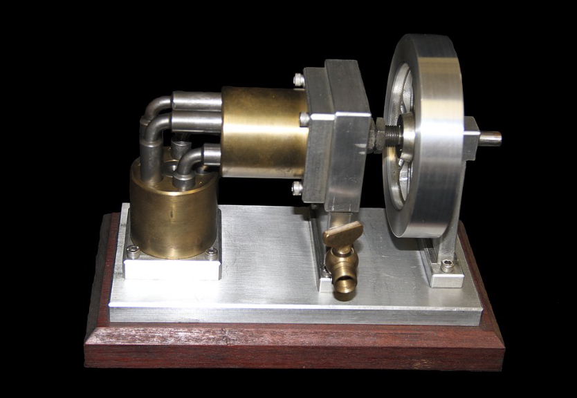
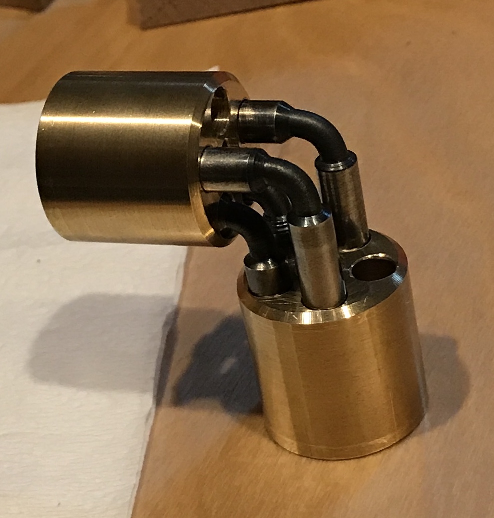
I started a project many years ago that was never finished. Nearly all of the parts were made, but the device would not turn with the first of five pistons fitted in the cylinders. It is an elbow engine with ten cylinders and five double ended pistons. The plans were purchased and then the dimensions were halved so it could be made on the Sherline. (Interestingly, I still have the materials for making a full sized version.) I also have the complete set of plans, which I must have purchased years ago. A photo of the engine that can be purchased from Bill Reichart is shown below.
The problem I was unable to solve when the project was abandoned was studied and a simple solution was found. The pistons need to be trimmed after being bent. After trimming the one bent piston about 1/16" on each end in the mill the two cylinders rotated smoothly. The other four pistons were already made and just needed bending.
Easier said than done. one end of a piston was held in the vise. The center reduced section was heated with a torch. A wooden dowel with a hole in one end was used to bend the piston. It broke near the vise-held end. Multiple attempts were made (nine!) to bend these pistons and others that were made anew. All ended in failure. After sleeping on the problem I came to a few conclusions. I had switched from using a dowel with a hole because it broke. I switched to a scrap of aluminum folded around a piston end and held with vice grips. This required two hands to operate effectively. So heating and bending were alternated. I also noticed all pistons broke near the piston end held in the vise.
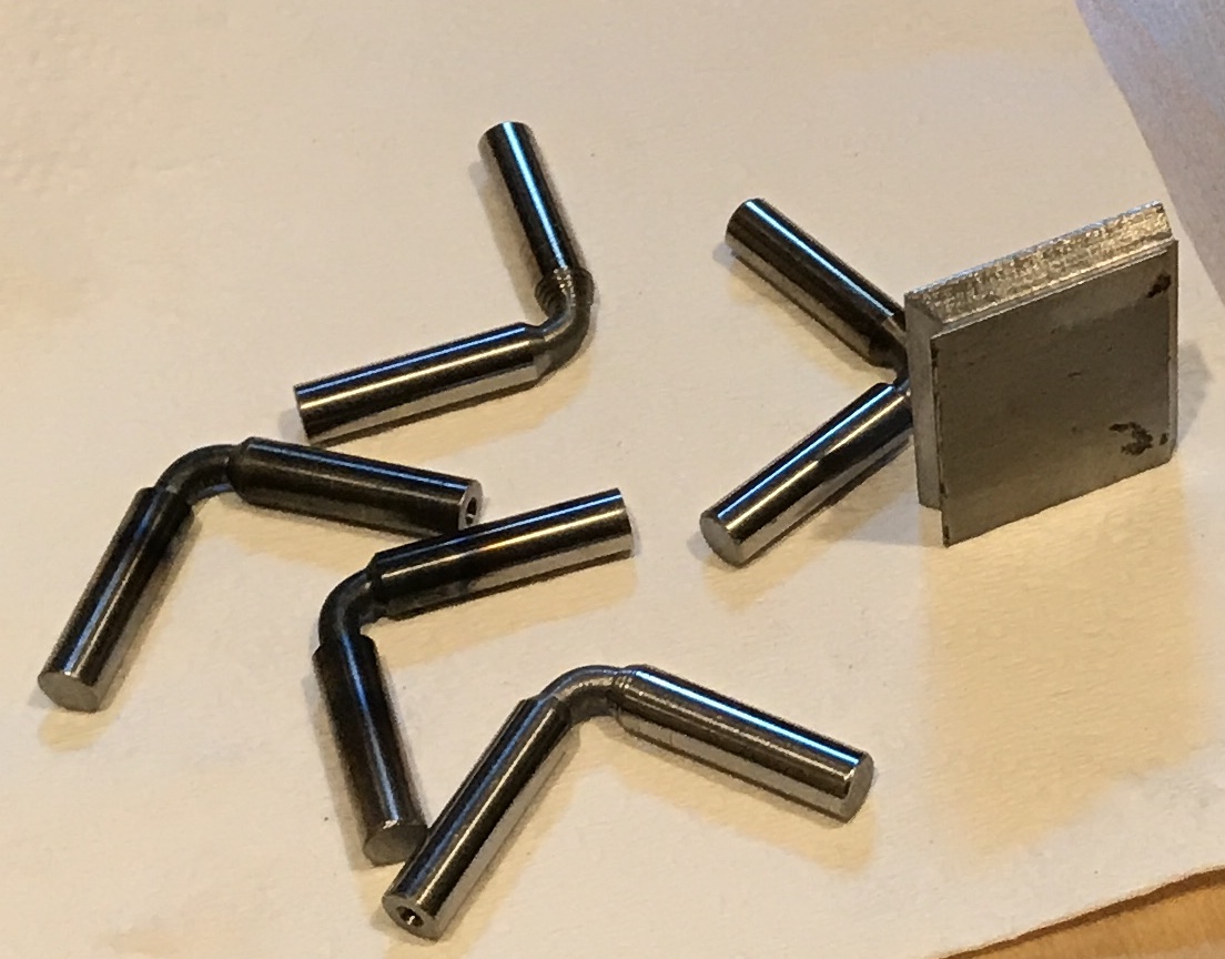
The end held in the vise needed better heating. The entire process needed to take place with constant heating. I found a scrap of 3/4" round steel and drilled a 1/4" hole in one end. The other end happened to be almost square and could readily be held with vise grips. I raised the vise end a little and pointed the flame downward while bending. All pistons bent well. A simple jig with adjacent vee grooves on two edges of a small square block was used to check the bend by measuring across said jig. The same jig was used to determine how much material needed to be removed from each end. Each piston needed to be about 1 5/16" long measuring from the outside of the other piston.
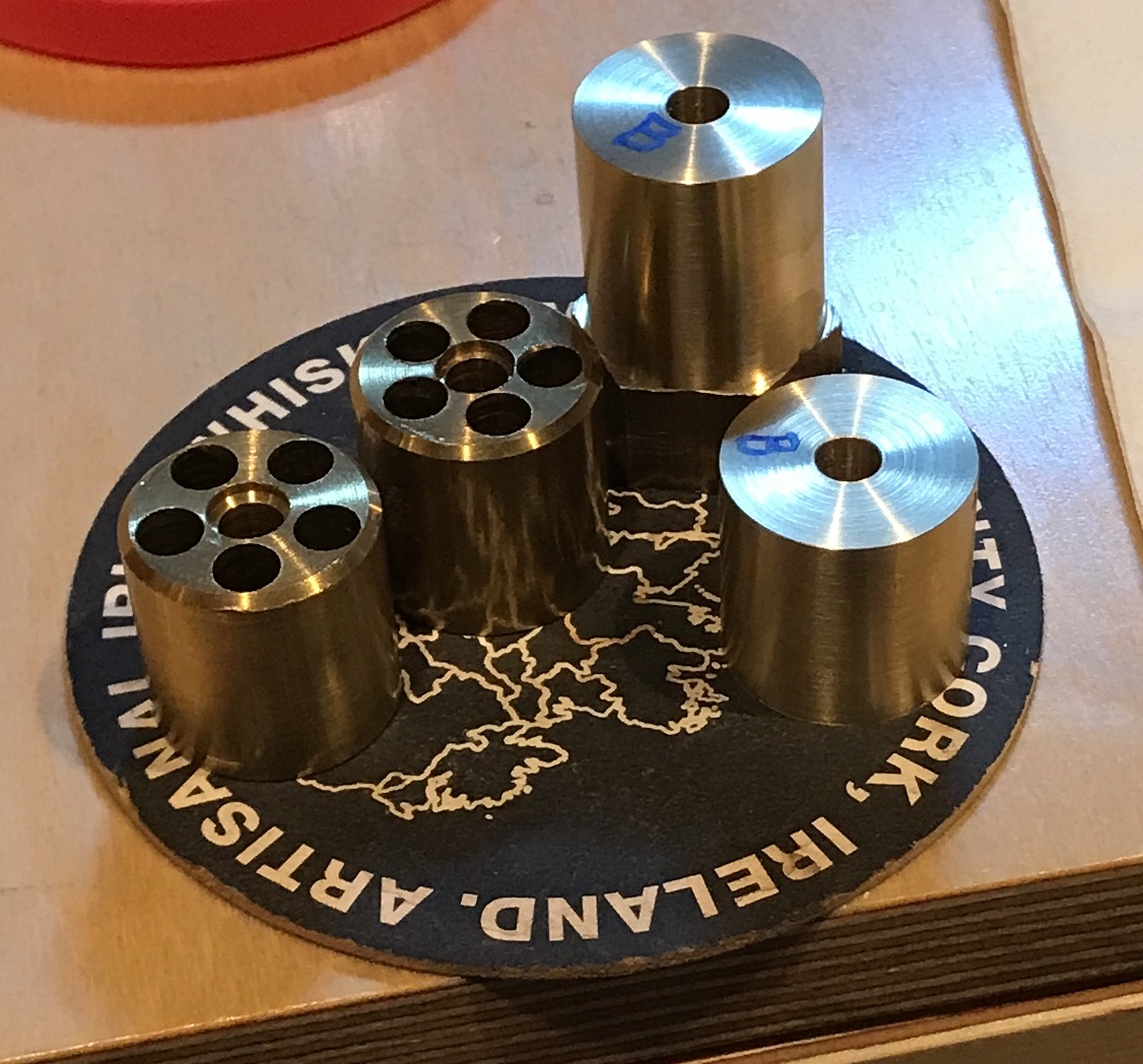
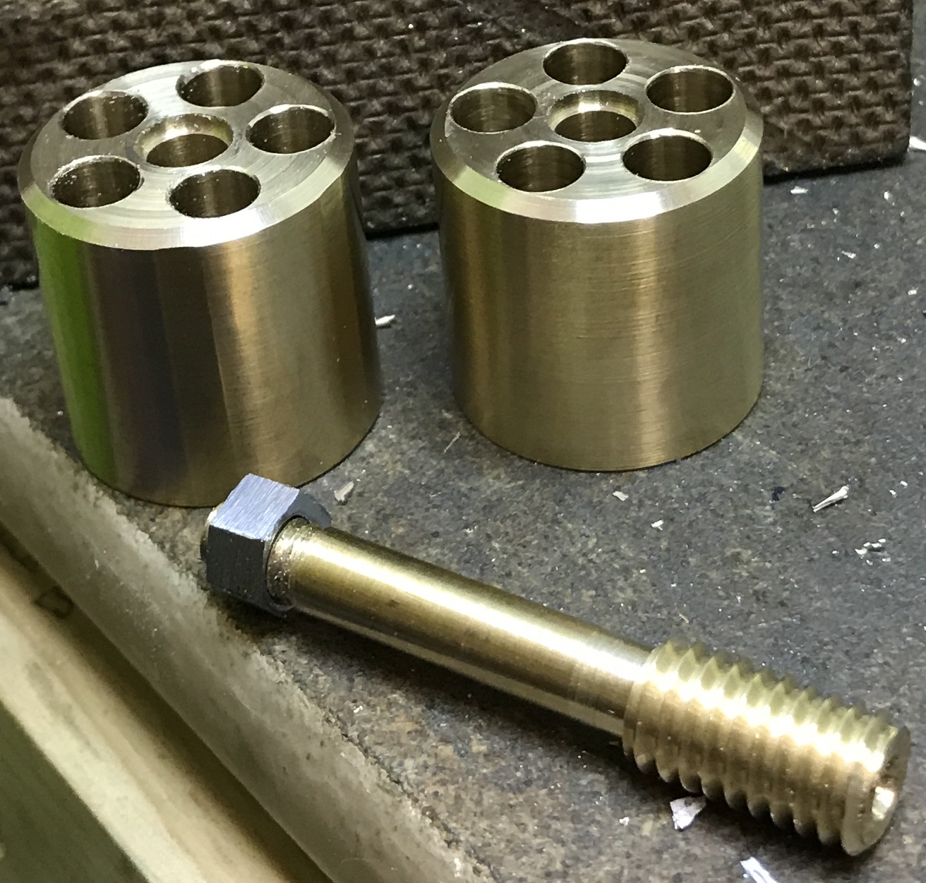
Each of the pistons when fitted into both cylinders and held in the engine frame worked smoothly. Two pistons simultaneously did not. Further study showed that the five holes in each cylinder block were not all on a 5/16" radius. Some were a little closer to the center hole and some a little farther away. Luckily I had 12" of 1" brass hex in the garage. A 2 3/4" length was cut off with the bandsaw. It was chucked in the three jaw chuck on the South Bend. It was faced and reduced to 1.000" diameter. The center hole was drilled with a C drill and reamed to 0.250". The first part was parted off at about 1 1/6". The faced end was marked bottom. This face must be perpendicular to the center hole. The second cylinder was made similarly, but was not parted off as there was too little material for holding. Two new and two old are seen below. The second cylinder blank was completed on the Sherline after removing most of the waste with a hacksaw. Both cylinders were heavily chamfered leaving a 1/16" chamfer.
A new adapter for the rotary table was made. A 2" length of 3/8" brass hex was cut and faced in the lathe. It was reduced to 0.250" for 1 1/4". The end was chamfered. The reduced end was held in a collet and the opposite end was faced and turned to 3/8". Both ends were center drilled. The lathe was set up for threading. First the large end was threaded 3/8-16 and then the small end was threaded 1/4-20 for 1/4".
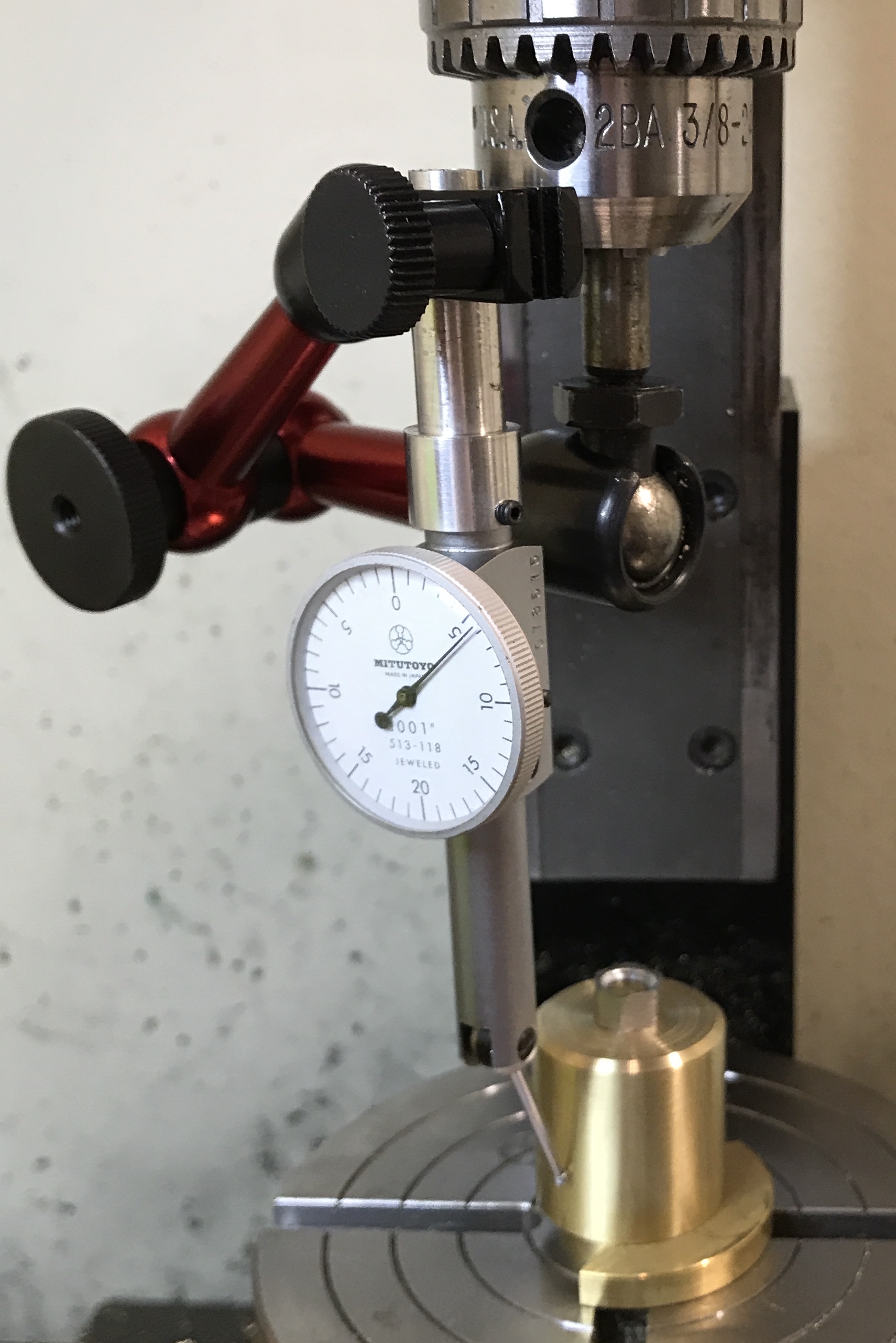
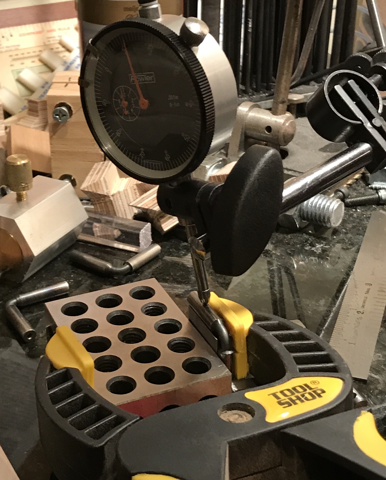
The rotary table was centered under the spindle using the dial test indicator held in the end mill collet. It was within 0,001" of center. Next a cylinder blank was placed on a scrap of brass and onto the adapter made above. This was screwed into the center of the rotary table. A standard 1/4-20 nut was too large by 1/8" diameter. A nut was locked onto a screw next to a second nut. After clamping in a vise each of the six faces was filed removing about 1/16" of steel. This tiny nut was lightly tightened on the adapter screw. Since there is a little wobble to the adapter in its hole, the cylinder needed to be indicated in as well. This was done with the dial test indicator held in an articulated arm as seen below. In this centering operation the table was not moved, but the cylinder was lightly tapped to center it. The tiny nut was then tightened. The cylinder was also within 0.001" of being on center.
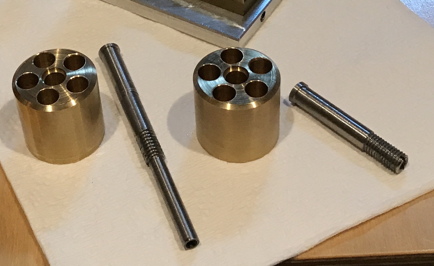
Each hole was started with a spotting drill. After drilling a hole with a C drill a 1/4" reamer was used to finish the hole. The table was then turned 72° to begin the next hole. This was repeated on both cylinder blanks. The completed cylinders alongside the adapter and tiny nut are shown below.
This (and larger) reamer has always been too long for this mill. Even with the added height block it limits the holes that can be made. It could never be used with the rotary table as it sets most parts too high. I finally cut it off for this work. I was able to saw about 2/3 through with a hacksaw, but it must have work hardened as the final third had to be cut with a cutoff wheel in the Dremel.
The next adjustment that needed to be made was to correct the press fits on the two shafts. Both were oversized at 0.252". A not so quick check of press fit tolerances for shafts indicated a difference between hole and shaft of about 0.0005" was more appropriate for this size shaft. (Placed a table of press fits in DevonThink.) The long shaft was centered in a four jaw chuck to less than 0.001". The appropriate section was reduced to 0.2505". The smaller shaft could not be held in the four jaw by the threads so it was held by the threads in a collet. This allowed most of the 1" section to be reduced to 0.2505". The rest was sanded with coarse sandpaper to less than 0.250". Consequently, for this shorter shaft only about 3/4" will be press fit, which is fine. Both ends were slightly oversize for the countersinks in the new cylinders. They are 5/16" in diameter, but the countersinks are only 0.290". For some reason my 5/16" end mill is undersized! Both ends were reduced to 0.290".
Two of the pistons are at 90°, but three are not and need to be bent again. It is very difficult to bend them and get the angle just right. All pistons were bent with heat and were very close as measured by calipers. There was still significant difficulty turning the assembly with two pistons installed.
Decided it was time for a different approach to measuring. The dial indicator was attached to the magnetic stand. A bent piston was clamped to the testing jig with a small machinist's clamp so one leg was held tight. The jig was clamped to a 1-2-3 block with the bottom edge flat on the granite plate. The indicator was used to check both exposed ends of the horizontal piston leg. Most were slightly closed by 4 - 6 thousandths. After measuring and labeling all five pistons each was taken to the vise, clamped between wooden blocks, and tapped lightly with the brass end of my new hammer. I could sense movement when the piston was held on the jig down to about 0.002". When it felt free of movement, the piston was remeasured. Four were within 0.001" of perfect. The fifth broke while attempting adjustment. I was able to fit the four pistons into the cylinders and turn them by hand, though not smoothly. Photos below show measuring and fit.
A fifth piston was made yet again. It was bent and tuned similarly. I was barely able to get all five pistons into the cylinders. They would not turn. Each of the pistons was checked against the jig. I could feel slight movement for all of them. I adjusted them with a hammer until I could no longer sense any movement. I was still unable to rotate the cylinders with all five pistons installed.
After struggling with clamping pistons between two loose pieces of wood, I made a pair of wooden jaws for the basement vise. A length of 3/4" Baltic birch plywood was cut to 4" and then two 2" wide strips were cut from it. Two more strips 1 1/4" wide were also cut. Two holes were drilled through te 2" strips and ten transferred to the thinner strips. These were drilled for #8 screws and the holes in the 2" strips were opened up to through holes for the screws. These holes were countersunk. The screws went through the 2" strips into the narrower strips. The narrow strips serve to hold the jaws to the vise. One wooden jaw had vee grooves cut across the face 1/8" deep with the mill at a 45° angle.